Crane without counterbalance

Large cranes are used in various loading and unloading operations, especially when carrying out large-scale construction work. All currently produced cranes (Png, Liebherr, KATO, Ivanovets, etc.) are equipped with counterbalances to ensure the stability of the crane when overturned when the load is lifted.
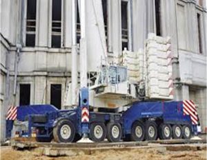 Fig.1 Crane with huge counterbalances.
We propose a new effective model of the principle of ensuring the stability of the crane, which uses one of the most powerful forces of nature – atmospheric pressure. For this purpose, the toes of the cranes coming out of the crane are replaced by joints with vacuum supports, which are compressed on the support platform under the influence of atmospheric pressure.
Cranes usually have protruding and adjustable supports, through which the crane is temporarily immobilized during operation, becoming an autonomous lifting installation. These pillars, located farther from the limit of the car, have a wider range of motion, increase the stability of the crane, as well as unload the brakes and tires from the moment when the load is lifted (Fig. 2).
In the model of crane stabilization proposed by us, the problem is solved as follows. The footrests of the tower cranes (Fig. 2) are replaced by a node of a structure patented by us [4], which, having a vacuum principle of operation, is equipped with a vacuum pump և performs the main function of a pillar. After removing air from the node cavity, due to atmospheric pressure, a large force is applied to the paw due to atmospheric pressure (Fig. 2). This force contributes to a significant additional increase in the stability of the crane.
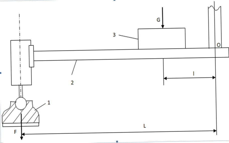 Fig. 2 Sketch of the crane protruding pillar
Replace the protruding support of the crane with the node shown in Fig. 3.
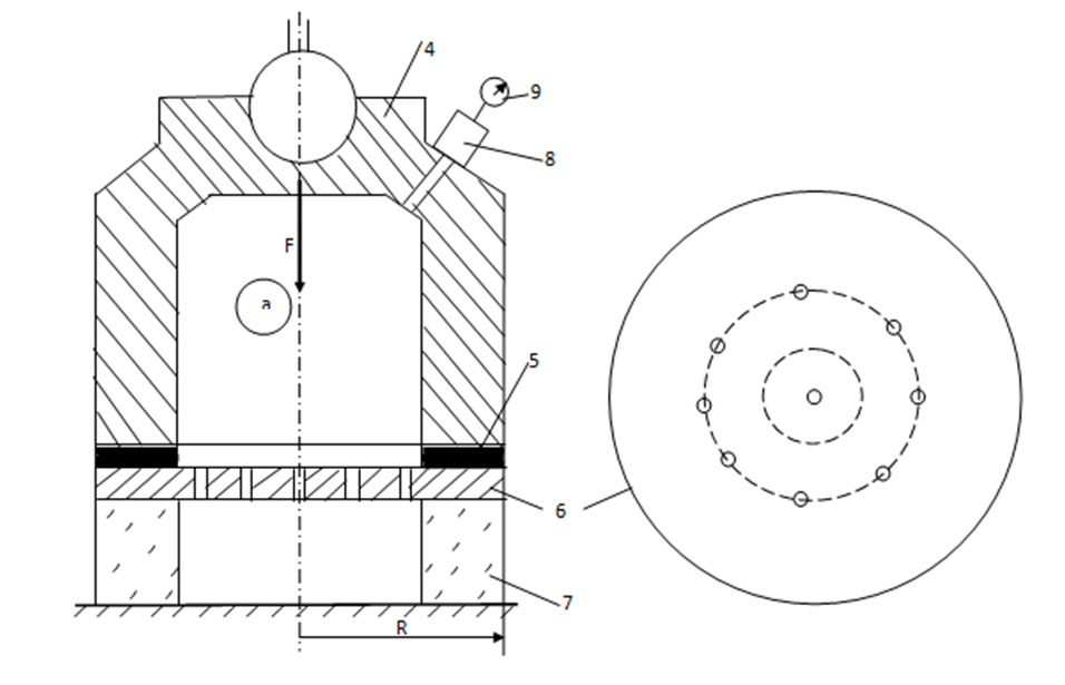 Fig.3 Scheme of vacuum support paw knot
The paw knot consists of the following elements: 4 – torso, 5 – gasket, 6 – steel plate with small holes, 7 – quite thick, elastic-flexible construction poroplast, 8 – vacuum pump, 9 – vacuum gauge.
When we lift the crane on the supports, under the force of its weight, 7 layers of poroplasty are deformed and pressed very hard to the ground, “merging” with it, thus ensuring (a) the ideal tightness of the cavity (working space). The pad (5) is provided to ensure that hermeticity. To improve airtightness, it is advisable to spray the ground with water under the pillars. Then, with the help of 8 vacuum pumps (a) we expel the air out of the cavity, creating a vacuum. (a) As a result of a vacuum in the working space under the influence of atmospheric pressure (Pm = 105 Pa) 4 bodies are pressed to the ground with a certain force F. This force greatly contributes to the stability of the crane. Even in the case of a medium vacuum (approximately 102 Pa), 4 bodies have a tremendous force. By changing the diameter of the steel plate, the required amount of force can be provided. The vacuum control defined at the station is carried out by means of a manometer.
In particular, at a radius of 6 plates R = 50 cm, the force acting on one pillar will be approximately 7.5 t, and on the four pillars together – 30 t.
Let us also evaluate the masses of the counterbalances of the atmospheric pressure forces F acting on the vacuum paws. The force L of the force F acting on the supporting support of the crane with respect to the turning point 0 is several times greater than the arm of the counterbalance G (Fig. 1). Therefore, from the point of view of stability, it corresponds to the increase of torque by the same amount. In the example given, even if L / l = 3, the sum of the atmospheric pressure acting on the vacuum pillars would be equivalent to 90 t of counterweight.
Along with the increase of the crane stability, in case of other equal conditions, it will be possible to increase the flight of the needle towards the pillars, which will be shown by the calculations based on Fig. 4. Therefore, in the case of a given load, perform a crane stability study (inversion with respect to point 0) in the case of ordinary և vacuum supports. In the case of a crane with ordinary supports, find the magnitude d of the needle d using the equilibrium moment equation. We will get it
d = (+) c /, (1)
where:
is the weight of the crane,
– is the weight of the counterweight.
In the case of the proposed design, the flight length will be equal
d = 2F (b + c) + (+) c /,
where F is the atmospheric pressure force acting on one node. Taking the minimum b = 3c, you will get the length of the flight
d = (+ + 8F) c /: (2)
Figure 4 Evaluation of the efficiency of the new model by flight length
Assuming even 8F = +, it turns out that the length d of the needle flight will be twice as long. And this is of great importance for large-scale work on the construction site.
Because in the case of vacuum supports, the magnitude of the forces acting on the paws is determined by the following expression:
F = R2 (Pm-Pv)
hence the radius
depending on the square law, that is, very fast.
The program aims to increase the stability of the crane by using a simple structure, inexpensive, efficient and reliable operation և easy-to-operate unit.
Increasing the stability of the crane, in case of stability of other factors, contributes to the expansion of the boundaries of the construction site served by it while working in autonomous conditions, which has a very important technical and economic significance.
By increasing the stability of the crane it will be possible to solve the following important problems:
1. Increase the mass (productivity) of the load (unloaded).
2. Expand the size of the area served by the crane.
LIST OF SCIENTIFIC PUBLICATIONS
1. Slavik Avagyan Mobile Crane without Counter weights. Standard Research Journals. Vol.2 (12) December 2014. pp.649-651:
2. Avagyan S.G. Autocran without anti-noise. Scientific-technical journal “Automotive design”. M .: “Mechanical engineering”. 2015 p.18:
3. Avagyan S.G. CRANE WITHOUT ANTI-CONTROL. XI All-Russian Union on Fundamental Problems of Theoretical and Appropriate Mechanics (Collection of Documents) Kazan 20-24 August 2015 Казань 2015. с. 69-70.
4. Patent, №375U, Avagyan SG RA, B66F11 / 00, F16B47 / 00, Crane, 26.03.2014